Getting started with the ESP32 microcontroller
Last updated on February 8th, 2025The ESP32 is a powerful and versatile microcontroller that’s perfect for DIY electronics projects. I’ve found them a useful addition to my home tech options, particularly due to their small size and low power consumption. If you’re a Raspberry Pi fan (as I am) the ESP32 offers a smaller, lower power option for simple scenarios such as sensor and smart appliance interactions.
In this guide I’ll walk you through the basics of getting started with an ESP32, from buying one through to a few basic programmes.
ESP32 SoC vs module vs development board
Whilst lots of ESP32s are available to buy, it’s worth being clear on the three different forms you are likely to find for sale.
ESP32 SoC (System on Chip)
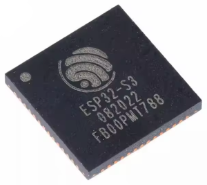
The heart of any ESP32 system is the ESP32 chip, known as an SoC (System on Chip). This can be purchased on its own for those wishing to build their own circuits from scratch.
ESP32 chips are about 7mm square in size.
ESP32 module
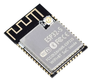
The next step up from the chip is an ESP32 module. Modules are a small, integrated unit that contains the ESP32 SoC as well as essential peripherals like a wifi antenna. The System on Chip and other key components are often covered by a protecting metal plate on the module.
ESP32 modules are usually about 26mm x 18mm in size.
I would still only recommend modules to those with experience of complex electronics and soldering.
ESP32 development board
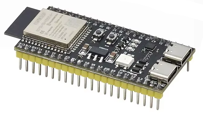
Whilst it is possible to make your own circuitry from an ESP32 chip, there are lots of ESP32 “development boards” out there, which come pre-soldered in a handy circuit board that may require no soldering at all, dependent on your needs. Many have USB power port(s) built-in, LEDs and header pins so you can connect your development board to any sensors etc through simple header cables if required.
ESP32 development boards vary in size but common formats can be around 57mm x 28mm in size.
What you need
Assuming you’re looking to getted started with ESP32 microcontrollers, starting with development boards, you’ll needed the following items:
- ESP32 development board: There are various models available, like the ESP32-S3 or ESP32-WROOM-32.
- USB cable: To connect the ESP32 board to your computer.
- Computer: For programming and uploading code.
- Arduino IDE: Whilst other options are available, I choose to use the popular Arduino platform for coding and uploading programs to the ESP32.
Step 1: Setting up the Arduino IDE
I’ve tried the Arduino Cloud Editor to avoid local installation before, but had security concerns allowing my web browser to access USB ports. I therefore recommend installing the IDE, which can be installed for Windows, Linux and MacOS.
As the Arduino IDE can be used on lots of different board types, you’ll need to download a package for ESP32 board in the Board Manager area of Arduino IDE.
- Download and Install Arduino IDE:
- Visit the Arduino IDE download page and install the IDE on your computer.
- Configure the ESP32 Board:
- Open the Arduino IDE and go to
File>Preferences. - In the “Additional Board Manager URLs” field, add this URL:
https://dl.espressif.com/dl/package_esp32_index.json. - Go to
Tools>Board>Boards Manager, search for “ESP32” and install the package by Espressif Systems.
- Open the Arduino IDE and go to
Step 2: Connecting your ESP32
- Connect your ESP32:
- Use the USB cable to connect the ESP32 board to your computer.
- Select the board and port:
- In the Arduino IDE, go to
Tools>Boardand select your ESP32 model. - Then, go to
Tools>Portand select the port to which your ESP32 is connected.
- In the Arduino IDE, go to
Step 3: Writing and uploading your first program
Now comes the exciting bit! A program written in Arduino IDE is called a “sketch”, so you’ll need to create and save sketches for your ESP32. Sketches have a .ino file extension when saved.
Sketches usually consist of two main functions:
setup(): This function runs once when the Arduino is powered on or reset. It’s used to initialize settings, such as pin modes or starting a serial connection.loop(): This function runs over and over again, allowing your program to continuously perform tasks.
Assuming your development board has an LED built-in, the below example will create and run some code to blink the LED. You can simply upload new code to overwrite this program when you’re ready to make your own.
- Create a new sketch:
- Open the Arduino IDE and create a new sketch by selecting
File>New.
- Open the Arduino IDE and create a new sketch by selecting
- Write a simple program:
- Let’s start with the classic “Blink” example. Replace the default code with the following:
void setup() {
pinMode(LED_BUILTIN, OUTPUT); // Initialize LED_BUILTINpin as an output pin}void loop() {
digitalWrite(LED_BUILTIN, HIGH); // Turn the LED on
delay(1000); // Wait for a second
digitalWrite(LED_BUILTIN, LOW); // Turn the LED off
delay(1000); // Wait for a second}
- Let’s start with the classic “Blink” example. Replace the default code with the following:
- Upload the program to your ESP32 development board:
- Click the upload button in the Arduino IDE. The IDE will compile and upload the code to your ESP32.
- You should see the built-in LED on the ESP32 blinking if everything is set up correctly.
Step 4: Exploring further
Another sketch I’d like to share with you is below. This is one I run on new modules to check their specification. This is partly for my records, and partly to check that the development board meets the specification that I bought!
This code writes details to the Serial Monitor, this lets you see the messages from your microcontroller. To view the data, you’ll need to turn on the Serial Monitor (Tools > Serial Monitor) and select the same baud rate as is used by the sketch (in this case 115200).
void setup() {
  Serial.begin(115200);

  Serial.println("-----------CORE-----------");
  Serial.print("Chip model: ");
  Serial.println(ESP.getChipModel());

  Serial.print("Chip version: ");
  Serial.println(ESP.getChipRevision());

  Serial.print("Number of cores: ");
  Serial.println(ESP.getChipCores());

  Serial.print("CPU frequency: "); Serial.print(ESP.getCpuFreqMHz()); Serial.println(" MHz");

  Serial.print("APB frequency: "); Serial.print(getApbFrequency() / 1000000.0, 1); Serial.println(" MHz");

  Serial.print("SDK: "); Serial.println(ESP.getSdkVersion());

  Serial.println("----------FLASH------------");
  Serial.print("Flash Chip Size: ");
  Serial.print(ESP.getFlashChipSize() / (1024.0 * 1024), 2); Serial.println(" MB");

  Serial.print("Flash Chip Frequency: ");
  Serial.print(ESP.getFlashChipSpeed() / 1000000); Serial.println(" MHz");

  Serial.println("----------RAM------------");
  Serial.print("RAM size: "); Serial.print(ESP.getHeapSize() / 1024.0, 2); Serial.println(" KB");

  Serial.print("Free RAM: "); Serial.print(ESP.getFreeHeap() / 1024.0, 2); Serial.println(" KB");

  Serial.print("Max RAM allocation: "); Serial.print(ESP.getMaxAllocHeap() / 1024.0, 2); Serial.println(" KB");

  Serial.println("----------PSRAM------------");
  Serial.print("Total PSRAM size: ");
  Serial.print(ESP.getPsramSize() / (1024.0 * 1024), 2); Serial.println(" MB");

  Serial.print("Free PSRAM: ");
  Serial.print(ESP.getFreePsram() / 1024.0, 2); Serial.println(" KB");
  Serial.println("----------------------");
}

void loop() {
}
Conclusion
The ESP32 is a fantastic low-cost platform to explore the world of microcontrollers and IoT. With development boards that are rich in features and extensive community support, you’ll find plenty of resources and inspiration for your projects.
Don’t forget to consider:
- Wi-Fi and Bluetooth: The ESP32’s built-in Wi-Fi and Bluetooth capabilities are some of its most attractive features. You can start experimenting with connecting the ESP32 to a Wi-Fi network or communicating with other Bluetooth devices.
- Sensors and modules: Connect various sensors and modules like temperature sensors, humidity sensors, and OLED displays to expand your projects
Happy tinkering!